How to connect and prepare the battery/BMS
Make sure the data connection from the GX device to the BMS is isolated, see also galvanic isolation. Otherwise you can damage your GX device and BMS, since the negative current will flow through the data cable, if the BMS disconnects the negative pole.
Since for some BMS the port labeling is a mess and not reflecting the real situation here are some useful instructions and links.
Daly BMS
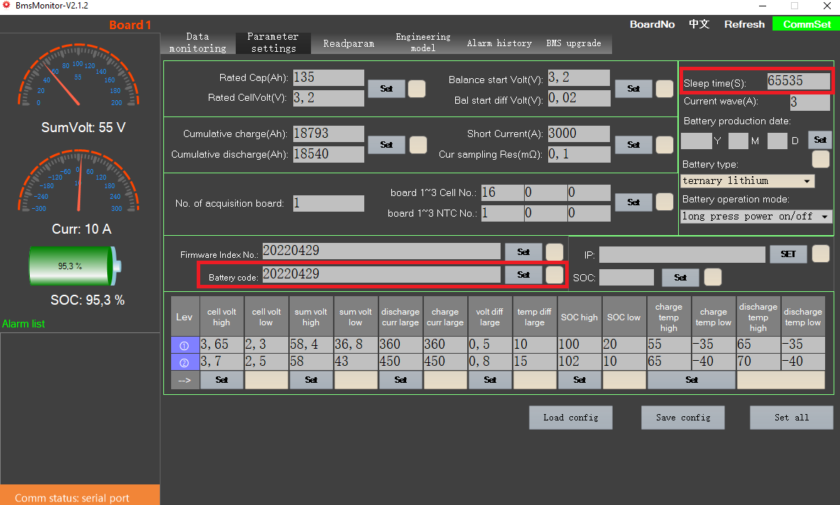
Connect your BMS via the PC software (BmsMonitor) and set the Sleep time(S) to 65535 to prevent the BMS from going to sleep.
If you are using multiple batteries you also have to make sure, that the Battery code is different on every battery.

EG4 LiFePower
For EG4 LiFePower batteries, you need to set your DIP switch pins to 1 for the battery connected to the Cerbo GX.
JKBMS
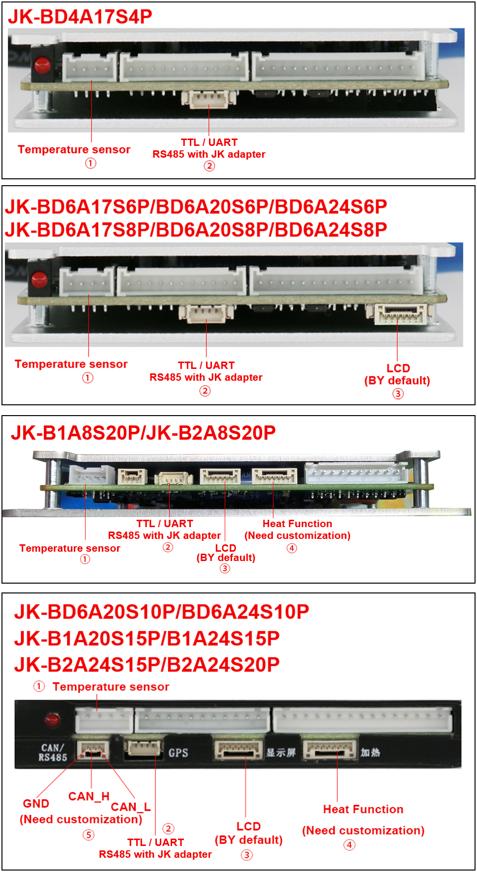
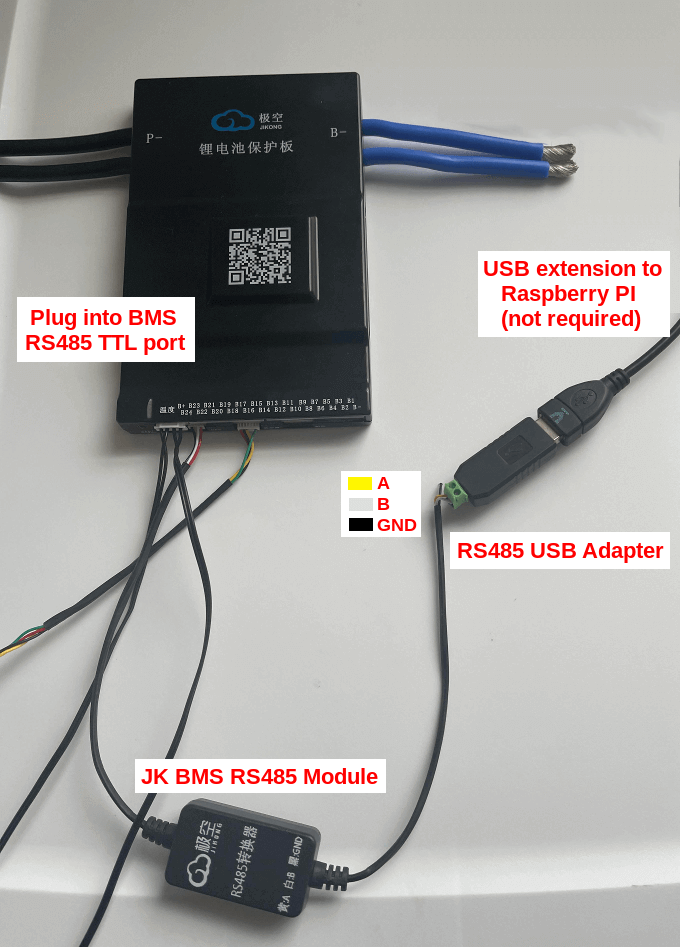
The JKBMS unfortunately has a wrong labeling. Here the correct pinout.


See also JK BMS JK-B2A8S20P RS-485 port / connector and New JKBMS "JK_DZ11B1A24S" (balancer only).
JKBMS PB Model (also know as JK Inverter BMS)
🌼🔗 Only if you want to connect multiple JKBMS PB BMS to the same RS485 adapter 👇
- Give each battery a unique address using the jumper on the front. Do not use
_ _ _ _, which corresponds to address0x00, as it sets the BMS into master mode, disabling RS485 communication. Then specify the MODBUS addresses in theconfig.iniat theMODBUS_ADDRESSESparameter.
For example, if you are using three batteries (battery 1 dip switches: 1: ON, rest off, battery 2 dip switches: 1: OFF, 2: ON, rest off, battery 3 dip switches: 1: ON, 2: ON, rest off) the parameter would be MODBUS_ADDRESSES = 0x01, 0x02, 0x03.
| Dip switch position | MODBUS address |
|---|---|
1 2 3 4 | |
_ _ _ _ | 0x00 |
‾ _ _ _ | 0x01 |
_ ‾ _ _ | 0x02 |
‾ ‾ _ _ | 0x03 |
_ _ ‾ _ | 0x04 |
‾ _ ‾ _ | 0x05 |
_ ‾ ‾ _ | 0x06 |
‾ ‾ ‾ _ | 0x07 |
_ _ _ ‾ | 0x08 |
‾ _ _ ‾ | 0x09 |
_ ‾ _ ‾ | 0x0A |
‾ ‾ _ ‾ | 0x0B |
_ _ ‾ ‾ | 0x0C |
‾ _ ‾ ‾ | 0x0D |
_ ‾ ‾ ‾ | 0x0E |
‾ ‾ ‾ ‾ | 0x0F |
-
Use a ethernet/CAT cable to connect all batteries via the RS485-2 ports. Both RS485-2 ports can be used.
-
Connect the first battery to your Cerbo/Raspberry using the RS485 to USB cable that came with the BMS.
-
In the JKBMS App ensure that the UART Protocol is set to the default
0/1. -
Reboot the system to apply the changes.
See also Is anyone using the new style JK inverter BMS with dbus-serialbattery driver?.