How to connect and prepare the battery/BMS
Make sure the data connection from the GX device to the BMS is isolated, see also galvanic isolation. Otherwise you can damage your GX device and BMS, since the negative current will flow through the data cable, if the BMS disconnects the negative pole.
Since for some BMS the port labeling is a mess and not reflecting the real situation here are some useful instructions and links.
UART/TTL (no daisy chain possible)
UART (Universal Asynchronous Receiver-Transmitter) is a serial communication protocol used for communication between devices. TTL (Transistor-Transistor Logic) refers to the voltage levels used in UART communication.
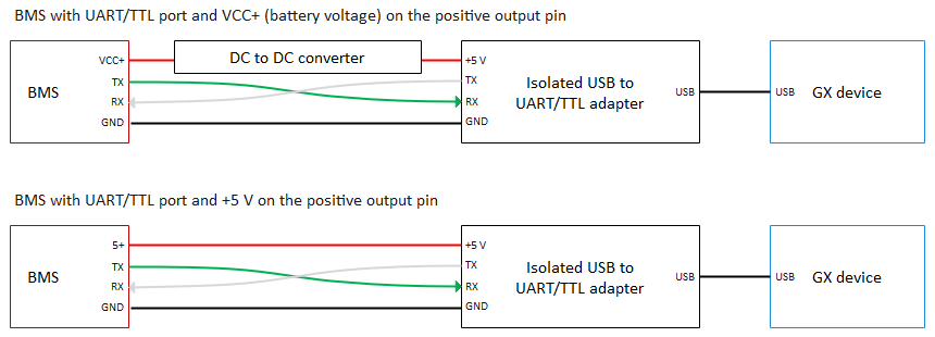
Ensure the voltage levels (5 V or 3.3 V) of your BMS are supported by the USB to UART/TTL adapter. Use an isolated adapter and power it correctly. Most BMS provide battery power VCC+ on the + pole of the UART/TTL connector. Measure it before connecting. You may need a DC to DC converter to match the voltage your isolated adapter needs.
Connect the wires in a device-to-device configuration. The main cable runs from the master (USB to UART adapter) to the BMS and contains three wires:
- TX (Transmit)
- RX (Receive)
- GND (common) for proper reference
The main cable should be shielded to prevent interference. Ensure that the TX of the master is connected to the RX of the BMS and the RX of the master is connected to the TX of the BMS.
Recommended adapters that are high quality and have been tested over a long period:
- USB SinglePort VE.Direct (affiliate link)
- USB Quadport VE.Direct (affiliate link)
RS485/Modbus (daisy chain possible)
Refer to the feature comparison to see which BMS models support daisy chaining.
RS485 is a differential balanced line over twisted pair, capable of spanning up to a few hundred meters. Be aware of voltage drops due to cable resistance and sensor power consumption.
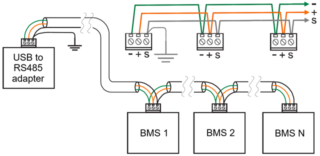
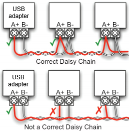
Connect the wires in a device-to-device (daisy chain) configuration:
- Avoid star or ring networks to prevent signal reflections.
- The main cable runs from the master (USB to RS485 adapter) to all BMS and contains three wires:
- A (DATA-)
- B (DATA+)
- GND (common) for proper reference
The main cable should be shielded. Ideally, the shield is separate from the 0 Volt line (GND), but they can be combined if the shield is free of voltage fluctuations.
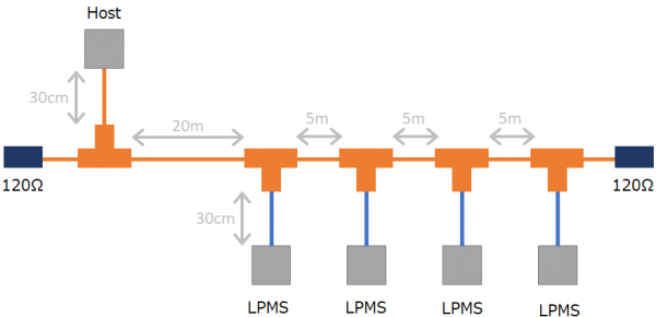
Use a termination resistor (120-130 Ω) between A (DATA-) and B (DATA+) if the line is longer than 10 meters.
See also this page.
CAN (daisy chain possible)
Refer to the feature comparison to see which BMS models support daisy chaining.
Do not forget to set
CAN_PORTin theconfig.ini.
First, you need to create the correct cable.
Victron Side
Refer to the VE.Can to CAN-bus BMS cables manual for instructions.
⚠️ Remember to use a 120 Ω resistor between CAN-H and CAN-L, or use a VE.Can RJ45 Terminator to terminate the line. Otherwise, it won't work. In some cases, you may also need to terminate the other end of the line.
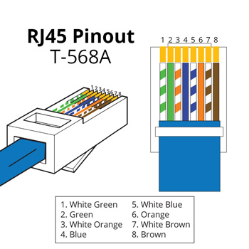
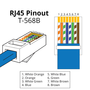
| Function | Victron VE.Can Side | RJ45 Pinout T-568A | RJ45 Pinout T-568B |
|---|---|---|---|
| GND | Pin 3 | White/Orange | White/Green |
| CAN-H | Pin 7 | White/Brown | White/Brown |
| CAN-L | Pin 8 | Brown | Brown |
BMS Side
Check your BMS manual for the correct pinout. If you don't find any, you could try to measure the voltages.
| Function | Voltage to GND |
|---|---|
| GND | 0 V |
| CAN-H | +3 V |
| CAN-L | +2 V |
Daisy chain
See also this page.
Bluetooth
No special preparation is required.
BMS configuration
Daly BMS
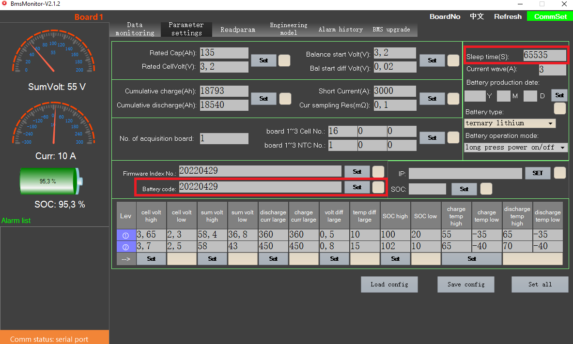
Connect your BMS via the PC software (BmsMonitor) and set the Sleep time(S) to 65535 to prevent the BMS from going to sleep.
If you are using multiple batteries you also have to make sure, that the Battery code is different on every battery.
RS485
🌼🔗 Only if you want to connect multiple Daly BMS to the same RS485 adapter 👇
-
Use Daly's BmsMonitor software (only for Windows) to set the board number. Using the mobile app
SMART BMSto set the board number will not correctly set it. -
Set a different board number for each BMS in the
BMS Toolssoftware -
Specify the MODBUS addresses in the
config.iniat theBATTERY_ADDRESSESparameter.For example, if you are using three batteries the parameter would be
BATTERY_ADDRESSES = 0x40, 0x41, 0x42.board number modbus address 10x4020x4130x4240x4350x4460x4570x4680x4790x48100x49110x4a120x4b130x4c140x4d150x4e160x4f
CAN
🌼🔗 Only if you want to connect multiple Daly BMS to the same CAN port 👇
- Download the Software
-
Visit this link and download the "PC Host Program for BMS."
-
Extract the downloaded file and run
JHB_serialport.exe.Note: Windows may block the program. If so, override the warning to proceed.
- Start the Software
-
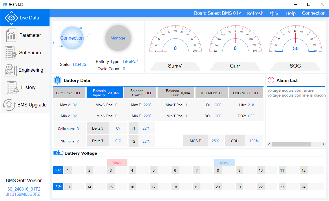
After launching the program, the main screen should look like this:
- Establish the Connection
-
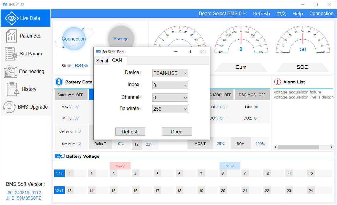
Select the appropriate connection method:
-
If you don’t have a compatible CAN adapter for your PC, use an RS485 adapter instead.
-
Choose the RS485 adapter from the serial port selection and set the baud rate to
9600.Note: The Peak CAN USB dongle may not work with this version of the software. Alternatively, you can use the older "BMSTool-V1.14.23" software, which is more complex but compatible.
-
View Live Battery Data
- Once connected, you should see live values from your battery.
-
Set the Board Address
-
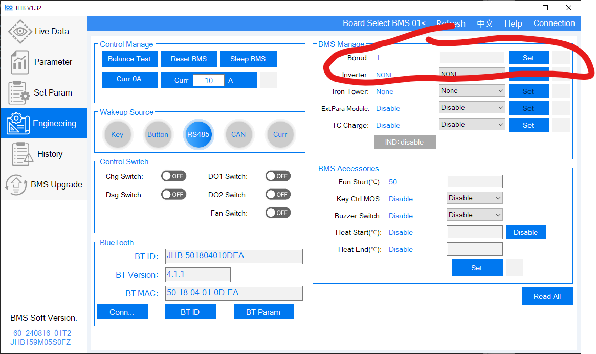
Navigate to the "Engineering" menu on the left.
-
Locate the Board Address Setting at the top-right corner of the screen.
-
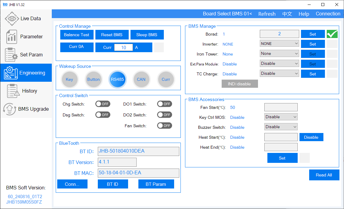
Enter your desired address and click "Set". A green checkmark will confirm the change.
-
-
Verify the Address
-
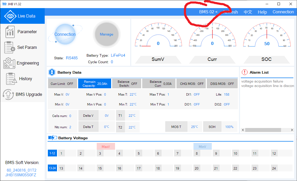
Return to the Main Screen.
-
Select your board number from the address dropdown at the top. You should see live values again.
-
-
Specify the CAN addresses in the
config.iniat theBATTERY_ADDRESSESparameter.For example, if you are using three batteries the parameter would be
BATTERY_ADDRESSES = 0x40, 0x41, 0x42.Board number CAN address 10x0120x0230x0340x0450x0560x0670x0780x0890x09100x0a110x0b120x0c130x0d140x0e150x0f160x10
Daren 485
See daren-485 on GitHub.
EG4 LiFePower
Also valid for:
|- Revov
|- TianPower
Set your DIP switch pins to 1 for the battery connected to the Cerbo GX.
🌼🔗 Only if you want to connect multiple EG4 LiFePower to the same RS485 adapter 👇
Set different battery addresses for each battery using the dip switches and then specify the MODBUS addresses in the config.ini at the BATTERY_ADDRESSES parameter.
For example, if you are using three batteries (battery 1 dip switches: 1: ON, rest off, battery 2 dip switches: 1: OFF, 2: ON, rest off, battery 3 dip switches: 1: ON, 2: ON, rest off) the parameter would be BATTERY_ADDRESSES = 0x01, 0x02, 0x03.
| Dip switch position | MODBUS address |
|---|---|
1 2 3 4 | |
_ _ _ _ | 0x00 |
‾ _ _ _ | 0x01 |
_ ‾ _ _ | 0x02 |
‾ ‾ _ _ | 0x03 |
_ _ ‾ _ | 0x04 |
‾ _ ‾ _ | 0x05 |
_ ‾ ‾ _ | 0x06 |
‾ ‾ ‾ _ | 0x07 |
_ _ _ ‾ | 0x08 |
‾ _ _ ‾ | 0x09 |
_ ‾ _ ‾ | 0x0a |
‾ ‾ _ ‾ | 0x0b |
_ _ ‾ ‾ | 0x0c |
‾ _ ‾ ‾ | 0x0d |
_ ‾ ‾ ‾ | 0x0e |
‾ ‾ ‾ ‾ | 0x0f |
See also EG Lifepower (Narada battery that uses Tianpower BMS) - Multi battery setup problems.
JKBMS
The JKBMS unfortunately has a wrong labeling. Here the correct pinout.
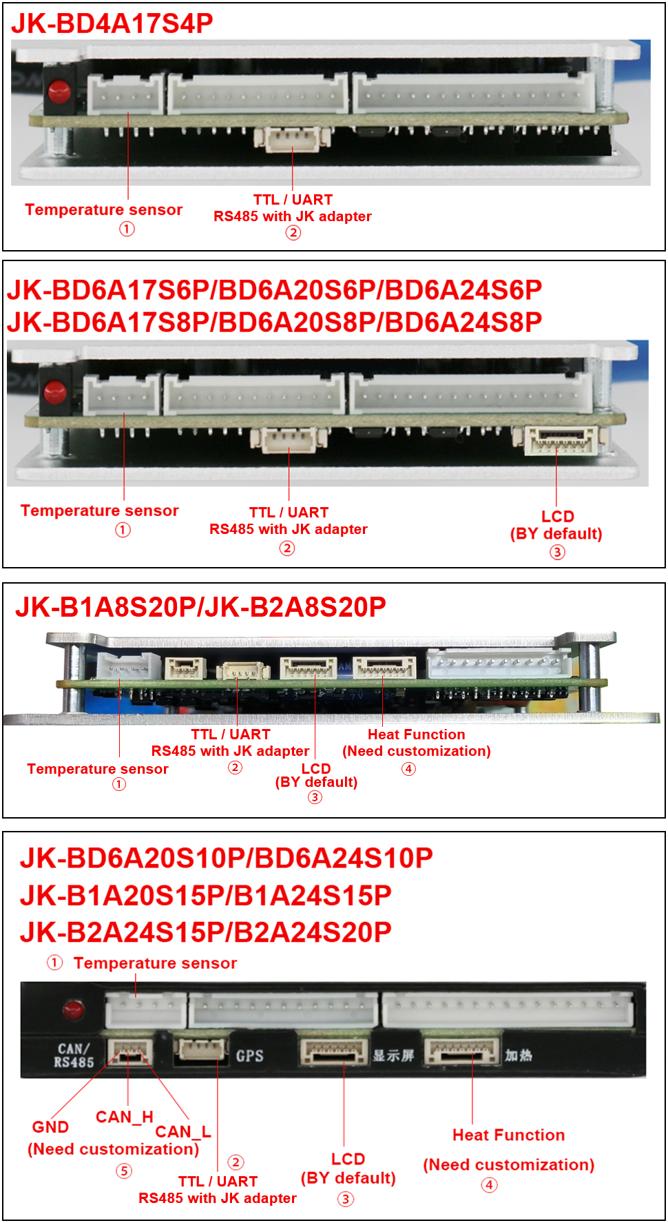
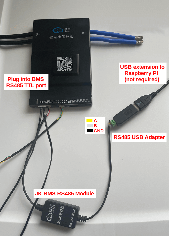
See also JK BMS JK-B2A8S20P RS-485 port / connector and New JKBMS "JK_DZ11B1A24S" (balancer only).
JKBMS PB Model (also know as JK Inverter BMS)
🌼🔗 Only if you want to connect multiple JKBMS PB BMS to the same RS485 adapter 👇
-
Give each battery a unique address using the jumper on the front. Do not use
_ _ _ _, which corresponds to address0x00, as it sets the BMS into master mode, disabling RS485 communication. Then specify the MODBUS addresses in theconfig.iniat theBATTERY_ADDRESSESparameter.For example, if you are using three batteries (battery 1 dip switches:
1: ON, rest off, battery 2 dip switches:1: OFF, 2: ON, rest off, battery 3 dip switches:1: ON, 2: ON, rest off) the parameter would beBATTERY_ADDRESSES = 0x01, 0x02, 0x03.dip switch position modbus address 1 2 3 4_ _ _ _0x00‾ _ _ _0x01_ ‾ _ _0x02‾ ‾ _ _0x03_ _ ‾ _0x04‾ _ ‾ _0x05_ ‾ ‾ _0x06‾ ‾ ‾ _0x07_ _ _ ‾0x08‾ _ _ ‾0x09_ ‾ _ ‾0x0a‾ ‾ _ ‾0x0b_ _ ‾ ‾0x0c‾ _ ‾ ‾0x0d_ ‾ ‾ ‾0x0e‾ ‾ ‾ ‾0x0f -
Use a ethernet/CAT cable to connect all batteries via the RS485-2 ports. Both RS485-2 ports can be used.
-
Connect the first battery to your Cerbo/Raspberry using the RS485 to USB cable that came with the BMS.
-
In the JKBMS App ensure that the UART Protocol is set to the default
0/1. -
Reboot the system to apply the changes.
See also Is anyone using the new style JK inverter BMS with dbus-serialbattery driver?.
Renogy
🌼🔗 Only if you want to connect multiple Renogy BMS to the same RS485 adapter 👇
-
Connect all batteries to the RS485 battery monitor or the BT2 to give the batteries individual addresses.
-
Disconnect the batteries from the RS485 battery monitor or the BT2 and connect them to the USB to RS485 adapter which is connected to the GX device.
-
Specify the MODBUS addresses in the
config.iniat theBATTERY_ADDRESSESparameter.For example, if you are using three batteries the parameter would be
BATTERY_ADDRESSES = 0x30, 0x31, 0x32.battery count MODBUS address 10x3020x3130x3240x3350x3460x3570x3680x3790x38100x39110x3a120x3b130x3c140x3d150x3e160x3f